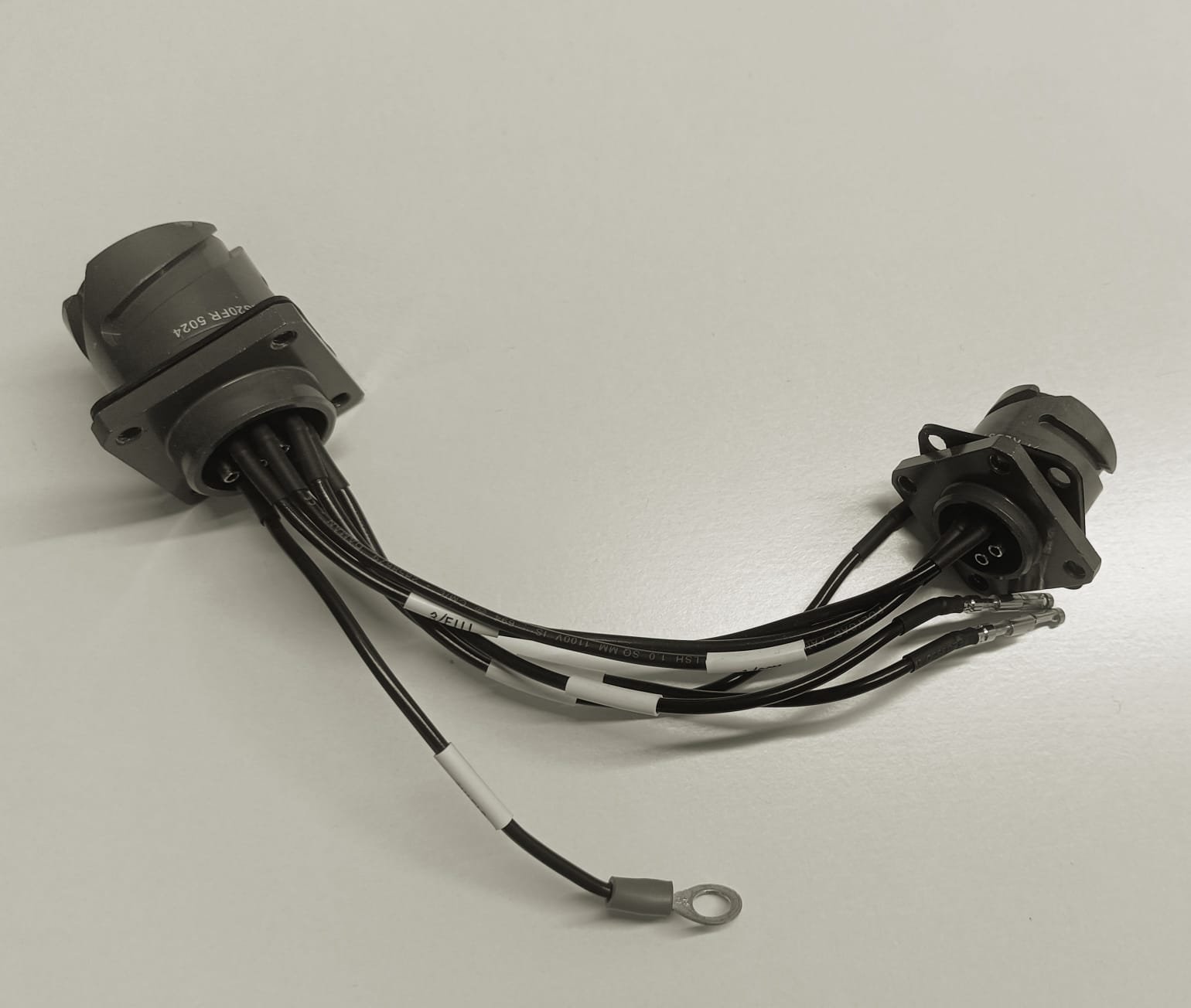
Circular connectors are widely used across mission-critical industries such as railways, defense, aerospace, and manufacturing due to their rugged construction and reliable performance in harsh environments. Therefore, proper wiring is crucial for the optimal performance of the connection.
Regardless of the connector you are using, the basic wiring steps remain consistent. Here is a comprehensive guide to help ensure that every connection you make is secure, efficient, and compliant with industry standards.
Tools & Materials You’ll Need:
· Circular connector (e.g., MIL-DTL-5015 or any other equivalent connector)
· Corresponding contacts (pins or sockets)
· Wire stripper
· Crimping tool in case of crimp connectors
· Soldering iron and solder (if required)
· Heat shrink boot (optional, for better insulation)
· Multimeter
· Backshell or strain relief (as per requirement)
Step-by-Step Wiring Instructions:
1. Prepare the Connector and Wires
Begin by identifying the pinout of your connector. Refer to the manufacturer’s datasheet or product manual to determine the correct pin numbering. This is especially crucial for connectors with multiple cavities or keying positions.
Next, strip the insulation from each wire. Typically, 5 to 7 mm of stripped length is workable. Do make sure you don’t nick the conductor strands while stripping.
Choose the right type of contact terminals (crimp or solder) based on your connector design and requirement. Using the wrong type can compromise the connection.
2. Attach Contacts to the Wires
Crimping Method:
• Insert the stripped wire into the crimp contact.
• Use a certified crimping tool to apply uniform pressure.
• Perform a tug test to ensure the wire is firmly held.
Soldering Method (if applicable):
• Heat the contact and apply solder to create a strong bond—avoid excess solder.
• Use heat shrink tubing after soldering for added insulation and mechanical support.
3. Insert Contacts into the Connector
With the wires securely terminated, push the contacts into the connector housing. You’ll typically hear or feel a click when the contact is locked in place.
Double-check the alignment and pin position using the pinout chart. Misaligned pins can cause signal loss or short circuits. Use a pin removal tool to make corrections if necessary.
4. Secure the Assembly
Attach the backshell or protective hood to shield the terminations. Where required, install a strain relief clamp—this is especially critical in high-vibration applications such as locomotives or armored vehicles.
5. Test Your Connections
Use a multimeter to verify proper continuity and power flow across all connected pins. Confirm that there are no short circuits between adjacent contacts. This is your final quality assurance step.
Tips for Reliable Wiring:
- Always follow the pinout precisely—mistakes here can be costly.
- Use the correct crimping or soldering tools for each contact type.
- In rugged environments, never skip strain relief or sealing.
- For moisture-sensitive applications, IP-rated security
At Jetronics India, we believe that the strength of any connection lies not just in the components—but in how well they’re assembled. A properly wired circular connector can withstand years of operation in the toughest environments, whether on railway systems, defense applications, or industrial equipment.
If you’re unsure about specifications or need support selecting the right connector for your application, our technical team is here to help. Write to us on – https://jetronicsindia.com/contact/


